2D Powder Diffraction Calibration Tutorial
- Jacob Filik
- Matt Taylor (Unlicensed)
- wnm24546
Quick Start!
Go to the Quick Start Guide!
Automatic, One-Click Calibration
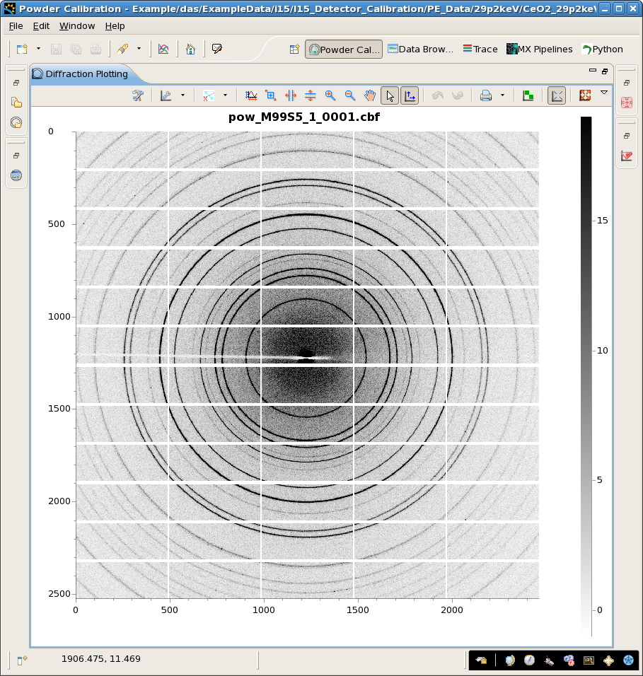
For images which contain the beam centre and multiple complete rings and have a detector tilt of less than 10 degrees - go for the Quick Start Guide
If Auto calibration doesn't work for your data, try Manual Calibration.
Manual Calibration
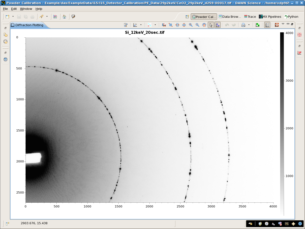
For images where the beam centre is off the detector, there are few complete rings or there is a high tilt, try Manual Calibration (requires starting guess for energy and experimental geometry)
Advanced Settings
There are 5 Options in the advanced settings:
Radius from the beam centre ignored - During automatic calibration, scattering around the beamstop can interfere with the peak detection, this value can be adjusted if first ring is very close to the beam stop or if scatter is interfering with the ring finding.
Set Minimum spacing for ring detection - The ring finding routine will skip rings that are very close together (to make the ring finding more robust), if the calibration pattern only has close spaced rings adjust this value to increase the number of rings found.
Number of points to find on each ring - How many points the ring finding tries to use.
Max search distance - Distance along the radius that is used for the peak fitting which finds the point on the ring. Reduce this number if the ring spacing is very close or there are rings in pattern which are not from the standard.
Fix the Detector Roll (beta)- The calibration routines produce a tilt angle and tilt angle rotation for the detector which map onto Yaw and Roll. If you know your detector is mounted with a roll of 0 or 45 degrees you can fix the roll value to get the full orientation of the detector relative to the sample.
Scripting Automatic Calibration in Jython
For images which contain the beam centre and multiple complete rings and have a detector tilt of less than 10 degrees - calibration can be scripted in Jython.
Theory
There are two different methods used in DAWN to calibrate powder diffraction images, Ellipse Parameter Calibration and Point Parameter Calibration. Here is a quick introduction to the calibration routine and the differences between the two methods.
Finding points of interest (POI)
The first step in the calibration process is to find the location of points of interest marking where the diffraction rings from the standard are in the image. DAWN takes a line profile across the ring, at many points around the ring and the peak fits the profile to find the maximum. The position of the maximum, transformed back into the image co-ordinates is a point of interest. The difference between the Ellipse Parameter Calibration and Point Parameter Calibration is what is done with these POIs to calibrate the experiment.
Ellipse Parameter Calibration
The ellipse parameter calibration assumes all the POI found on a single diffraction ring can be fitted to an ellipse (hence the tilts must not be extreme and enough of the ring must be on the image to get accurate ellipse parameters). The method used to calibrate the image from the ellipse parameters can be found in this article: Complete elliptical ring geometry provides energy and instrument calibration for synchrotron-based two-dimensional X-ray diffraction Michael L. Hart , Michael Drakopoulos , Christina Reinhard , Thomas Connolley Journal of Applied Crystallography (Vol: 46, Pages: 1249 - 1260) DOI: 10.1107/S0021889813022437
The Ellipse Parameter Calibration works best using multiple images at a very well defined separation and requires no indication of the energy or distance the measurement was taken at. The beam centre and detector tilts are explicitly calculated during this calibration procedure, and so cannot be fixed.
Point Parameter Calibration
The Point Parameter Calibration is a more basic approach than the Ellipse Parameter Calibration and simply relies on the fact that each POI found on a standard ring corresponds to a specific q value, and that doing an initial "by-eye" alignment gives a close energy/wavelength and experimental geometry.
From these initial energy and geometry parameters, q values for each point of interest can be calculated. During the calibration, the energy, distance, beam centre and detector tilts are adjusted until the model POI q values best match the expected standard q values.
Since this process does not rely on the accuracy of an ellipse fit, the Point Parameter Calibration can be used for partial rings or very high tilts, but has the dis-advantage of needing a good set of initial parameters. Since all parameters are determined by fitting any can be fixed, for example if the energy and beam centre have already been determined.
Configuring a new calibration standard
In progress....